Quadrupedal Locomotion: Hidden Modes of Failure
Overview
In this project, I explored some conventional locomotive techniques using a four-legged robot, the objective being a stable implementation of a quadrupedal crawling motion. Throughout this process, I discovered unstable modes of the system that were missing from the original problem formulation. Design changes were made to mitigate these instabilities.
Design Phase
Electronics
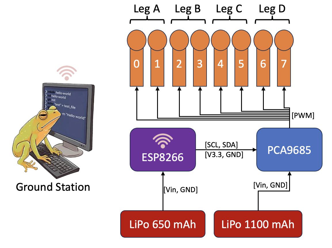
The electronic design centers around the capabilities of the microcontroller. It must be able to interface with other components using I2C protocols, as well as receive commands wirelessly as the system should be able to move around untethered. The ESP8266 is a compact microcontroller with onboard wifi communication was an ideal choice for this project
The PCA9685 servo controller can support 16 servo channels over via an I2C connection with the ESP8266. This additional component is necessary because the current requirement for 8 servos will exceed the limit of the chip.
Additionally, two LiPo batteries were selected to prevent surges and drains of the control signal - 1100mAh for the servos and 650mAh for the ESP8266.
The Robot
This is a small quadruped with 2-DoF controlled wirelessly via an ESP8266 Microcontroller. A PCA9685 was used to drive the motors via an I2C connection.


Software
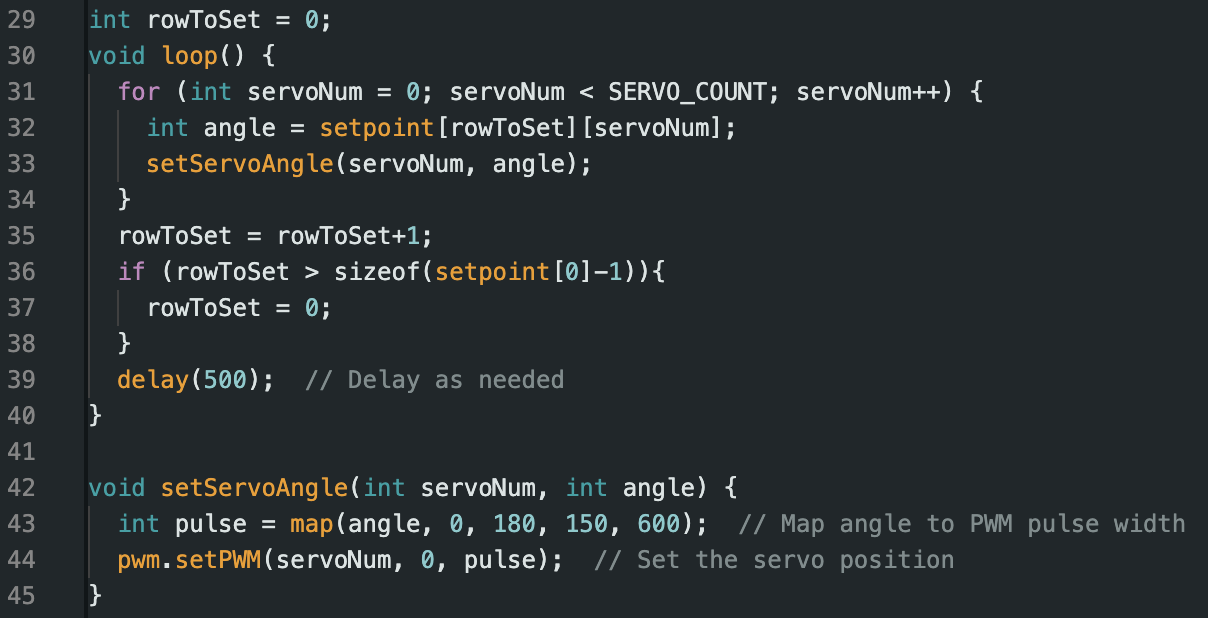
The primary role of the microcontroller is to carry out instructions generated from our algorithms in MATLAB. The ESP8266 is flashed setpoint angles for all 8 servos, which are updated every timestep until the termination of the program. Debugging a wireless device is very difficult when connection cannot be established. A significant challenge for me was setting up wireless communication, as this was my first time utilitzing IOT hardware. I accomplished this over many baby-steps towards the goal, eventually landing on netcat for the ground station and UDP for the microcontroller.
Locomotive Algorithms
Stability Condition - Triangle Constraint
When a leg is in motion, our tripod is stable if the CoM lies within a triangle defined by the positions of the other three legs
The IVP is set up so that the triangle constraint holds for all foothold states throughout time.

For each leg, there is an additional unpowered joint that translates the elbow rotation into vertical motion. The shoulder joint provides movement over an arc.


The two most common quadrupedal locomotive techniques found in the natural world are crawling and trotting. As shown in the above diagram, the crawling technique requires 3 points of contact while the trotting technique requires only 2. While trotting is faster, there is an inherent instability in having only two feet on the ground. Even with a well tuned feedback controller, mistakes made in state estimation such a changing environments, harsh lighting, and traversing deformable terrain could lead to a fall. Crawling ensures a constant tripod stability throughout the movement. In future projects, I hope to include sensors and an IMU which are needed to implement feedback control. For this project , I will only be testing a crawling technique.
Gait Planning - Direct Method
The two most common methods for gait planning are the direct method, (solving an IVP), and reinforcement learning. While reinforcement learning can lead to more robust handling of uneven surfaces, the direct method will be used for it’s simplicity
MATLAB was used for planning due to its built in solvers. Waypoints are defined by the user, which are then discretized into pose targets for each step. A gait can be found after fully defining the IVP with our constraints and assumptions.
Sending Instructions Wirelessly
The resulting Setpoints.csv is collapsed into a packet of sequential integers. This packet is sent to the microcontroller over WiFi using UDP protocol. The first integer in the packet tells the microcontroller how many integers are to follow.
After reception, the microcontroller parses the instruction sequence into degree setpoints for each of the 8 servos, stepping through time until completion.
Testing Phase
Crawling
Trotting
Galloping
What Happened to Tripod Stability?
Addressing the Problem
Slower movement speed means lower torque magnitude
Accurate CoM location: this helps determine that location of static, dynamic, and unstable regimes
Well tuned motor controllers: The control objective for tuning is good reference tracking. Poor reference tracking will increase uncertainty of the magnitude of oscillation.
Smoother reference signals to improve tracking (sin wave vs square wave)
Final Comparison
Original Crawling Test
Why is this Behavior Important?


While the robot walks straight, an oscillation builds to the point where the foothold opposite of the moving leg loses contact with the ground. I consider this a failure is it negates the optimizations in the gait planner.
For trotting, only two legs are in contact with the ground at a time. The robot veers off course as imperfection in the build and servo calibration go uncorrected. Onboard sensors to maintain good tracking with the gait planner reference.
Galloping occurs when all four legs are in motion at once in a leaping forward motion. The servo are not powerful enough to executed this motion, however, I did have fun programming it manually.
This mode of failure is hidden by our assumption that inertia is negligible and that the CoM position is well known. Tripod stability only exists in a static analysis. In reality, there are still dynamics at play. While the they can be very complicated (especially incorporating the pitch and roll of the chassis), a simple dynamical model can be formulated as impulses on the pendulum initiated by each step. If steps occur at a resonant mode, the building rotational inertia can exceed our tripod stability criteria, causing the robot to fall on itself every time it lifts its leg to take a step. This resonant frequency is found via the height of CoM with respect to the foothold at ground level. Failure can occur at twice the gait frequency approaches this mode in an alternating step scheme.
Your system can actually carry out the motion that was planned
Correct for signal noise in sensor data: If you know your robot oscillates at 0.4 Hz while walking, then you will easily be able to filter it out from sensors. This simplifies the representation process, which is a great computational bottleneck if current motion planners for robotics.
